
Bleepler Kit Manual
⋆
Bleepler Kit Manual ⋆
A quick bleepler kit update for 2026
All kits sold after January 2026 come with the updated mkIV main board and a transistor. I advise not populating the transistor into the board until the speaker and capacitor step. Orientate the transistor as depicted on the board.
(integrating this information into the current instructions is proving more work than I had anticipated but will be done eventually)
First Things First:

So you bought a Bleepler kit and want to know how to assemble it correctly like the pros do?
Well, you are in the right place for that!

Inside the packaging there should be 23 individual items. We’re about to go on a journey. Don’t worry — it shan’t hurt unless you art uncareful.
Firstly, we’ll need to make sure we have adequate tooling!

Things required to get this job done:
solder
soldering iron
side cutters
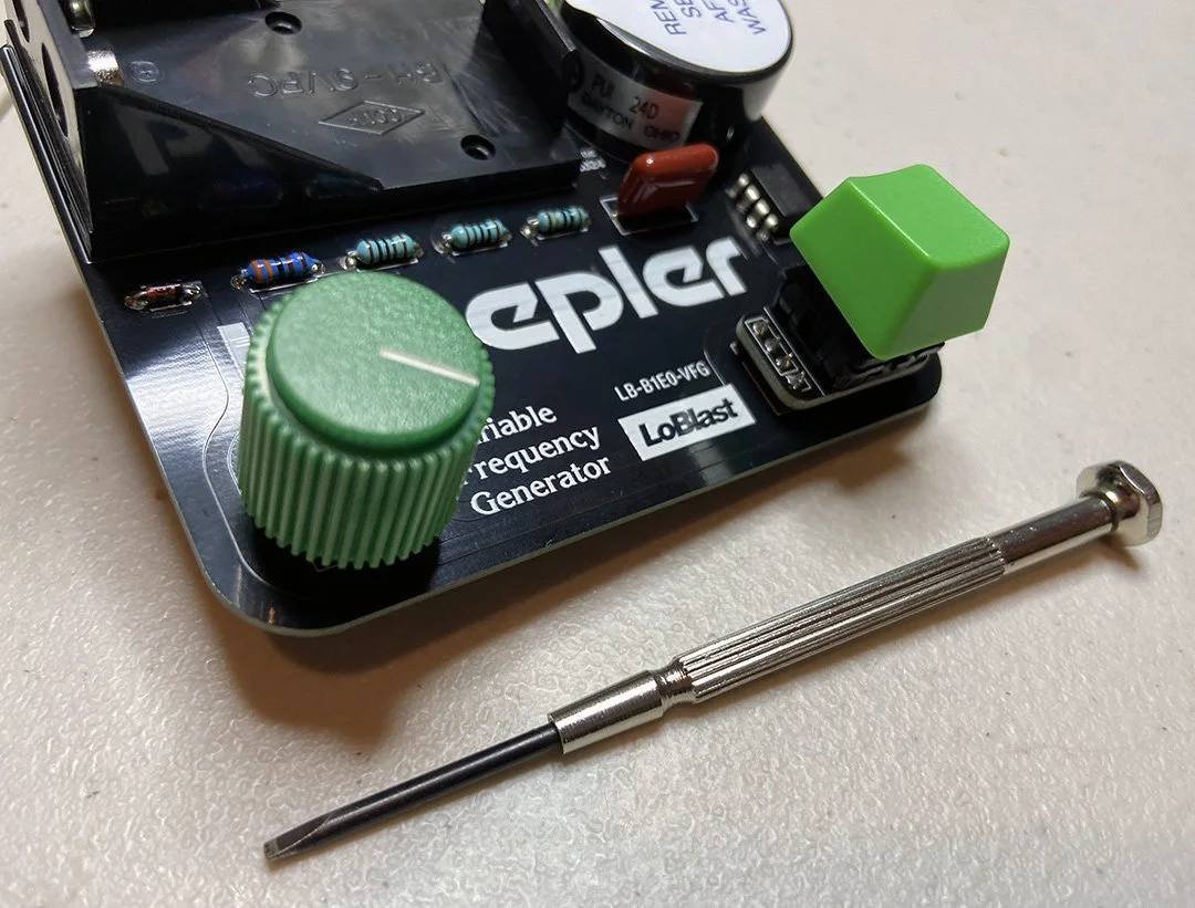
tiny flat-head screw driver
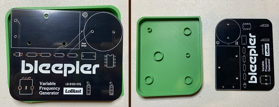
Separate the main PCB and the plastic chassis (pictured below). They should be set in the kit in a way that keeps them from getting stuck together before its time. If the PCB gets stuck inside the chassis before the components are soldered on it becomes very, very difficult to separate them.

Next apply the battery cover to whatever 9v battery you have readily available. If you do not have a 9v battery readily available then you will need to acquire one before your Bleepler will become fully operational. The smaller battery terminal sits closest to the far side of the Bleepler. Apply the LoBlast branded power supply cover as pictured below to ensure a conformist appearance.
FIRE UP THE IRON!!
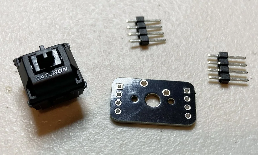
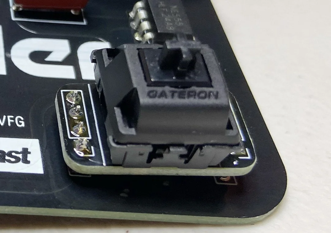
We will start by doing the switch plinth sub build. Grab the switch plinth PCB (it’s the small one), the two 4 pin headers, and the key switch.
Push the switch into the PCB. With your iron hot & ready, solder the switch leads to the board.
Some switch brands are a snug fit and others are sloppy. You may need to prop these two parts upright to succeed if using cherry mx key switches.

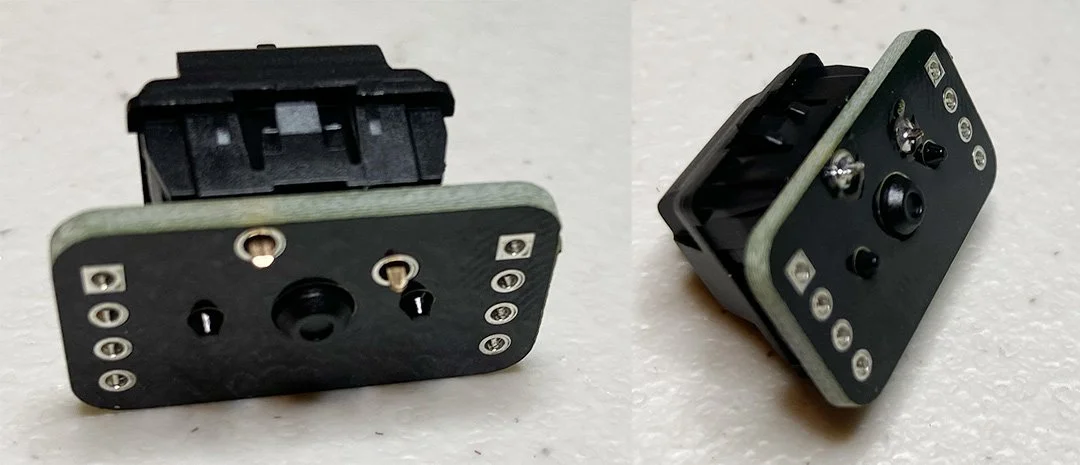
Place the two 4 pin headers into the main PCB so that the shorter leads are pointing up and the long leads are in the holes.
Place the switch and smaller board onto the pins. Solder the smaller board to the pins. Do not solder the lower pins to the main board.
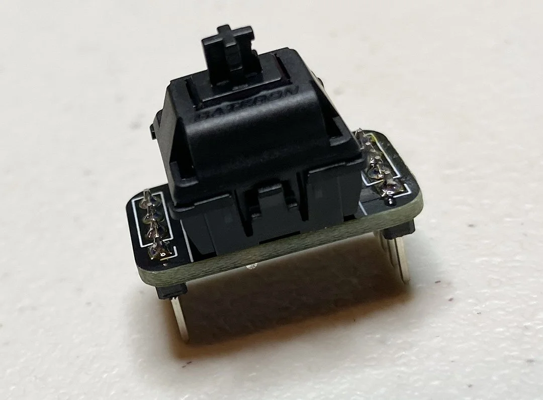
The switch plinth sub build is now complete! Set this unit aside and out of the way for future use.
NOW THE MAIN BOARD

Now we are going to put the diode, the four resistors, and the 555 microchip into the main board. There are three values of resistors: the 3.3k has two oranges stripes, the two 1k’s have all black and brown stripes, and the 10 has a single golden stripe.
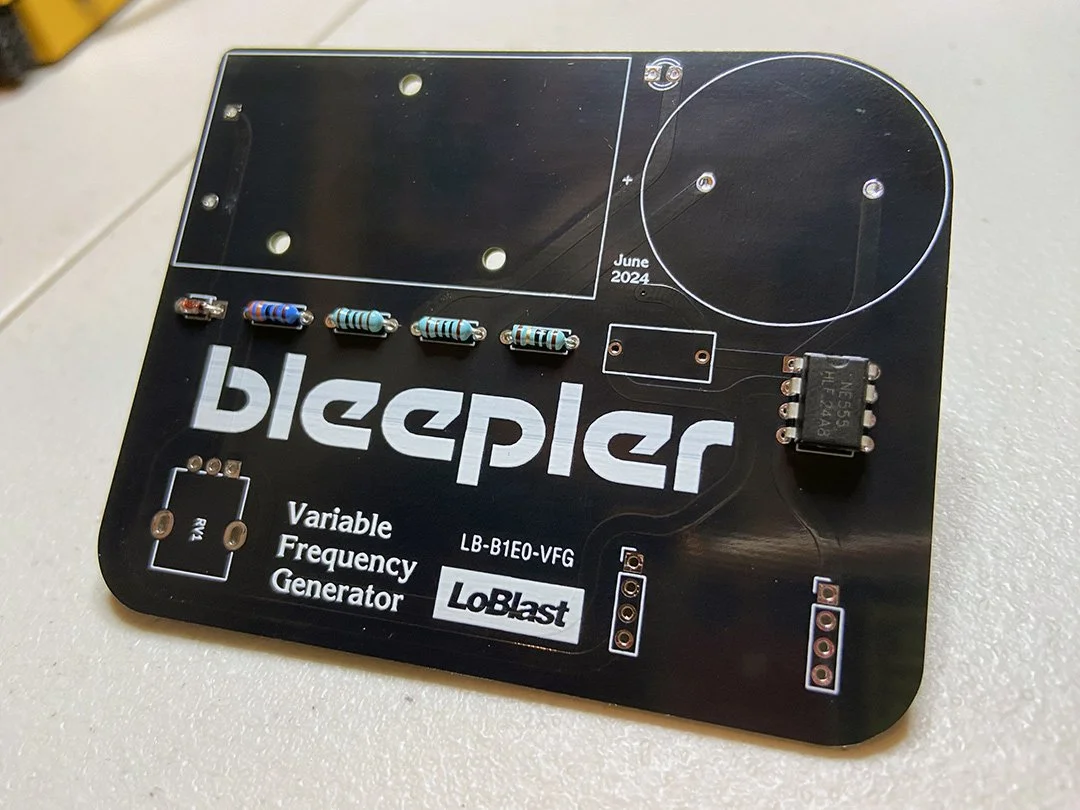
The black stripe on the diode needs to align with the screen printed stripe on the board. The resistors’ direction doesn’t matter but it’s very important they are in the correct order from left to right: one orange striped guy, then the two black and brown striped guys, and finally the gold striped guy.
Make sure the notch in the 555 microchip aligns upwardly with the notch in the screen print on the board.
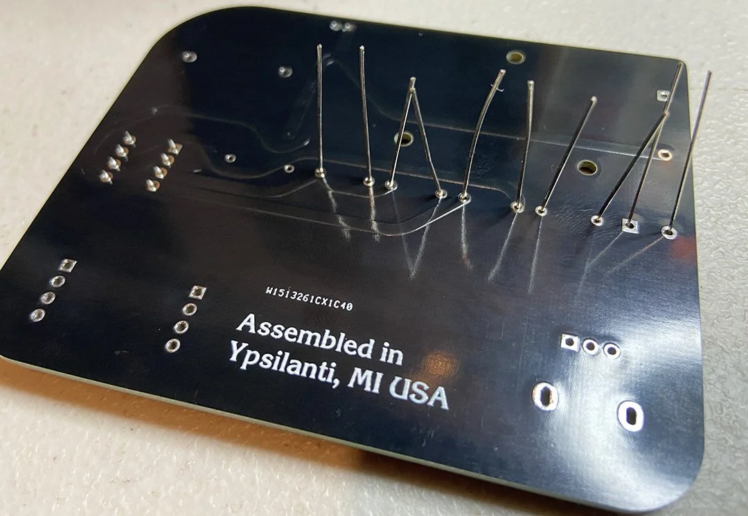
Now flip it all over and solder all of these components into place. You may want to angle the board with force to ensure the components are flush with the board on the other side.
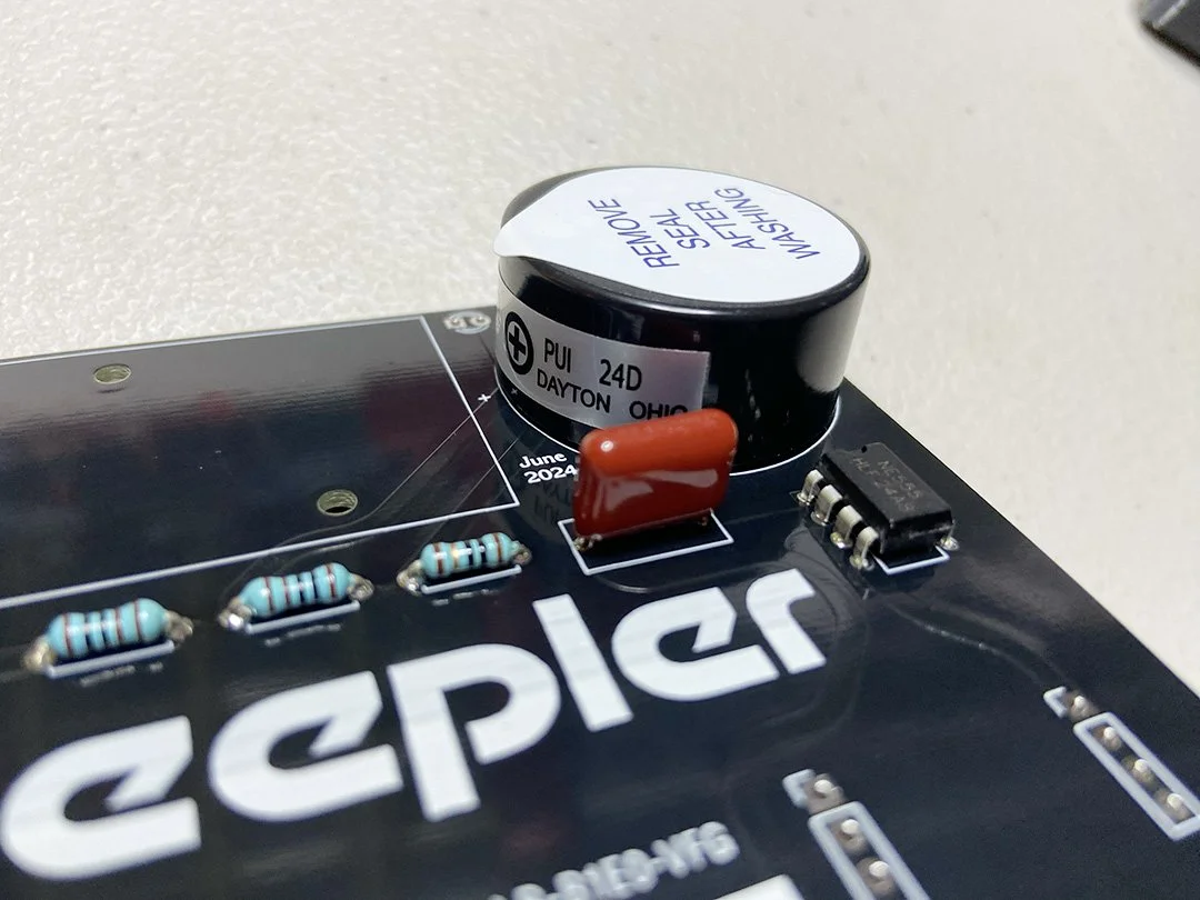
Next is the speaker and film capacitor. Make sure the positive terminal of the speaker is to the left or it will release the magic smoke when you power it on! The film capacitor can go in either way but we usually hide the print on the back side.
Flip and solder.

Place the poster putty on the bottom side of the battery holder away from the pins.

Slide the pins into their holes and firmly squish the poster putty between the battery holder and the main board. This helps to keep the battery square with the unit.
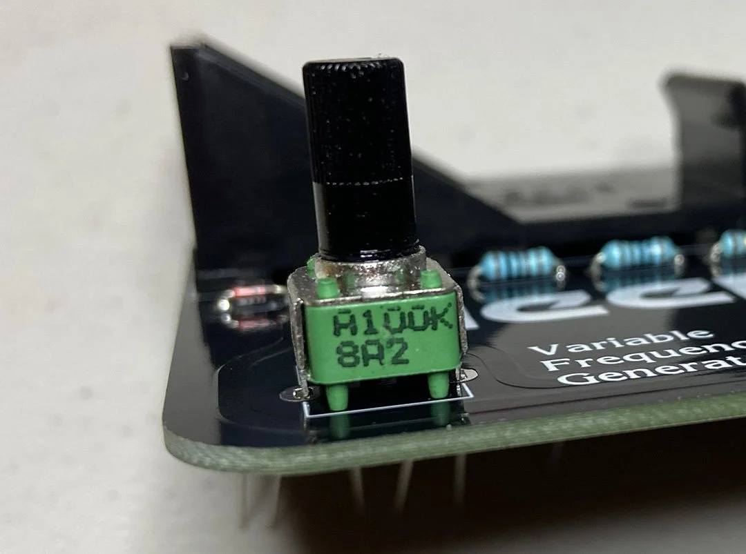
The potentiometer can be a bit tricky and require a bit of force. The three main pins interact with the circuit and are easy to insert. The two side supports often need to be squeezed inwards so they align correctly and snap into their holes. Make sure the little green legs are flush with the board.
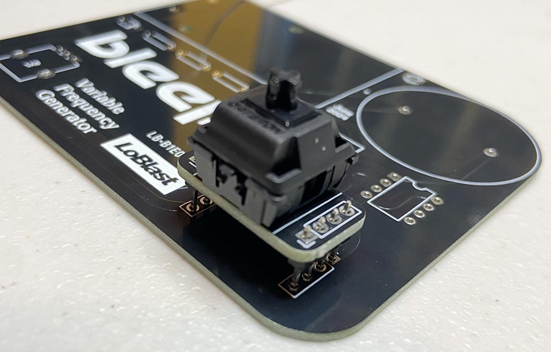
Grab the switch plinth we made earlier and put it in the board.
It’s now time for more soldering!
Make sure the switch plinth is flush with the board.

Also make sure the pot’s side supports are soldered into place so they don’t come loose in future rigorous play sessions.
LET US DECORATE

Oh no we forgot the LED!
The long lead goes to the right.
Go ahead and solder it in.
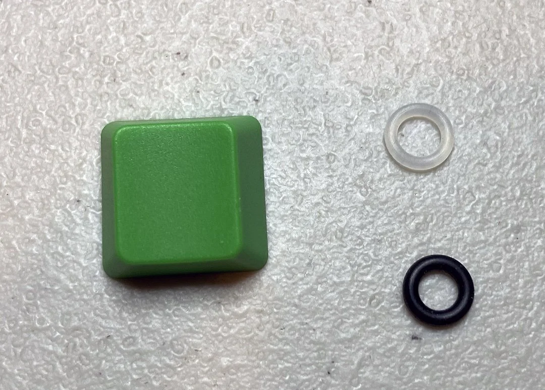
Find the small silicone ring. This is a key dampener. It reduces clicking and clacking sounds while mashing the button. It will randomly either be translucent or black in color.
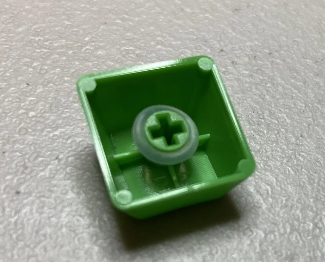
Place the dampener around the inner shaft of the key cap.
Then shove the key cap onto the key switch that is mounted on the switch plinth which is mounted plainly upon the main board.
Turn the potentiometer to its max clockwise position. Grab the knob. Using your small flat-head screwdriver, back off the knob’s set screw if it won’t slide down on the pot’s shaft. While pointing the knob diagonally right-down, tighten the set screw firmly.
TIME FOR THE PETICURE

Using your side cutters, remove all the excessive leads from the bottom. Everything needs to be trimmed back except for the potentiometer and the 555 chip.
BIRTHING YOUR BLEEPLER
Insert the battery into its home.
Press the button. You should see the LED light up and faintly hear the speaker bleeplering.

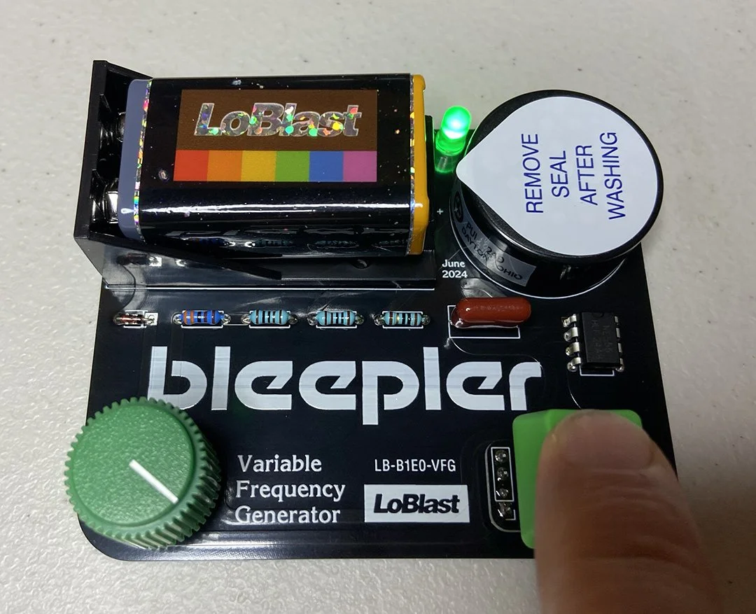
While holding the button, grab the tab of the “REMOVE SEAL AFTER WASHING” seal and remove it.
You should be hearing your Bleepler come to life with a big WEEEAAAAOWWW!!!
